GEEN 1400: Prevent-A-Dent
Abstract
Have you ever struggled to park your car in a tricky driveway or stressed over hitting objects as you pull into a tight parking space? Certainly, countless drivers encounter such situations on a daily basis. While newer cars have built in sensors that avert this issue, for older cars there is a lack of precise external instrumentation that exists to address such problems. Furthermore, cosmetic and structural damage to one’s home and/or vehicle can be both financially and emotionally straining.
Enter: Prevent-A-Dent. Prevent-A-Dent is a smart home system that provides a convenient, relatively cheap, and reliable way to aid drivers by providing real-time distance data in tight parking spots. Consisting of at least one ultrasonic distance sensor module and a central display connected via bluetooth, data from the sensor is sent directly to the LED display, easing driver worries. Both modules can be mounted at any location in a garage or around a home with our variety of mounting designs and the portability of the distance sensor device, allowing for optimal viewing and detection. The Prevent-A-Dent system allows drivers to save money, time, and emotional stress in the long run, thus offering a simple solution to common parking struggles.
Video of Prevent-A-Dent in action
Audience
Drivers of all ages and demographics facing tight garages and tricky driveways can stand to benefit from Prevent-A-Dent. Furthermore, those with older cars who do not wish to add a sensor to their vehicle in fear of decreasing retail value would greatly benefit from our system, since our sensors are mounted in locations in or near the garage rather than on the car in question, a key difference from current systems available on the market. Even those that own newer cars with built-in sensors could utilize Prevent-A-Dent when they have visitors attempting to park in their driveway or garage.
Design Requirements
- Accurate distance sensing to within +/- 1”
- Bluetooth connection between distance sensor and display
- Ability to visibly display single and double digit integers
- Ability to update rapidly in real-time
- Mountable at any location in a garage or driveway
- Easy/long-lasting sources of power
Design Process
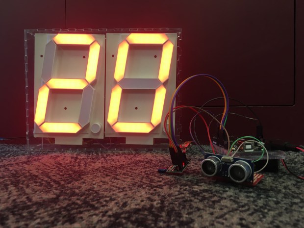
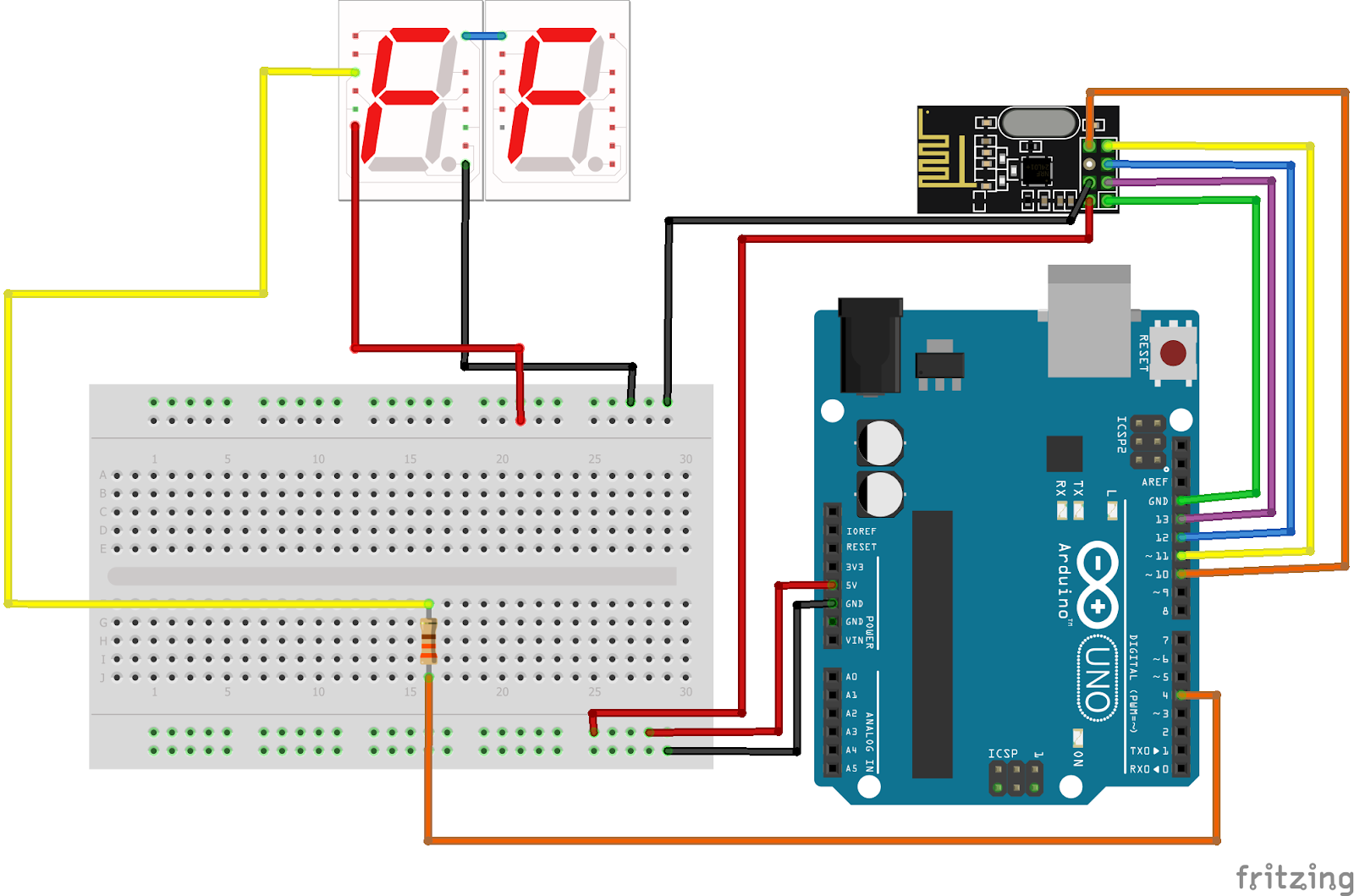
Our design consists of at least two separate modules, one containing the ultrasonic distance sensor and one consisting of the LED display, with the option to add further, identical distance sensor modules for multiple tricky objects or locations. Both modules also have NRF-24 bluetooth radios for data transmission and reception and are connected to Arduino Unos for coding and power. In our final design iteration, we soldered the majority of the connections in each module to reduce size and ensure reliability.
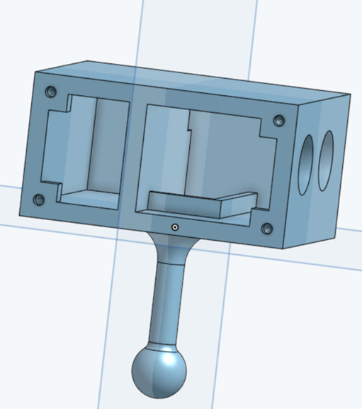
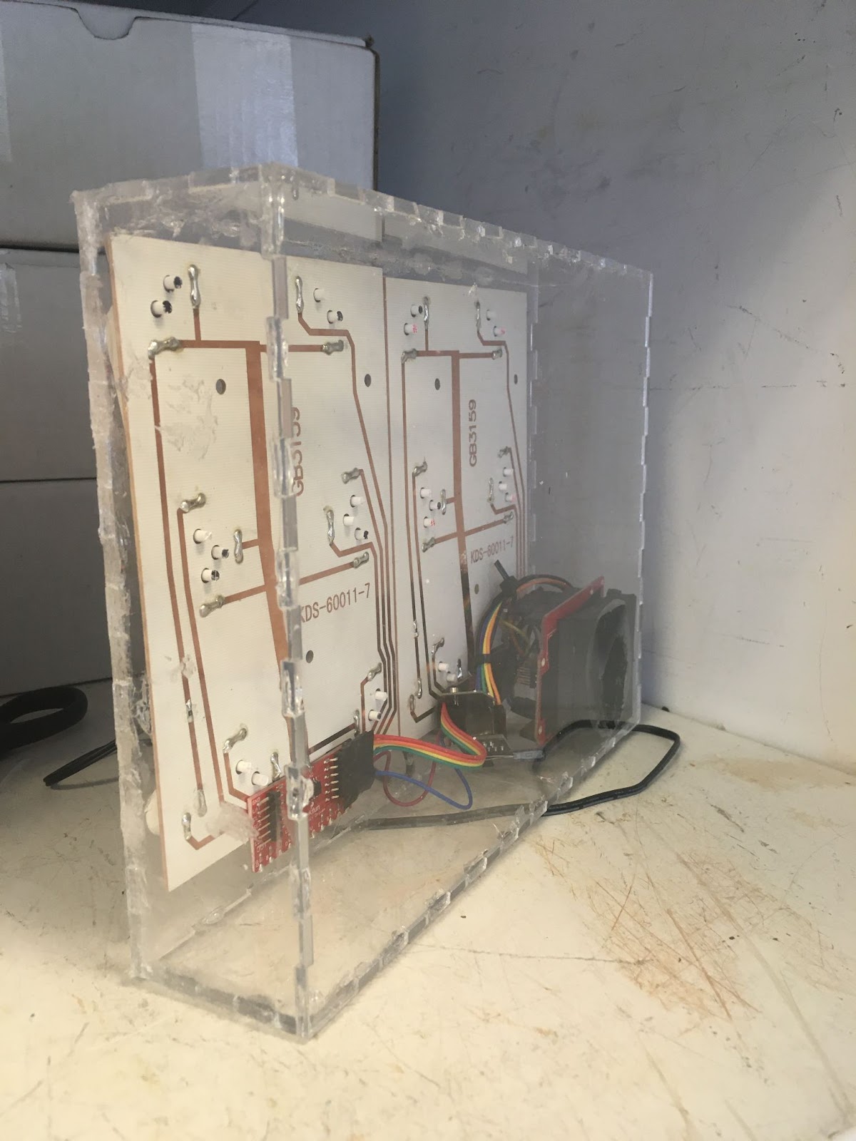
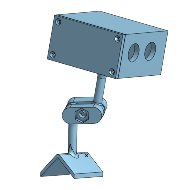
The module containing our ultrasonic sensor is encased in a 3D printed box on a ball-and-socket joint mount in order to allow for full range of viewing and setup. The power for this module comes from a 6V battery supply that lasts approximately 25 hours. The module with the LED display is held in a laser-cut acrylic box, glued together with epoxy and requires a nearby wall-socket, as it is powered by a 20V adapter as required by the display.
For our distance sensor, we chose to use HC-SR04 ultrasonic sensors rather than other common distance sensors such as infrared or LIDAR, due to their effectiveness given their significantly cheaper cost and high accuracy within an applicable range (15’, much further than needed for our purposes). While ultrasonic sensors can be affected by loud noises and don’t work reliably at extreme angles, we found in our testing that they were suitable for our purposes and had exceptional precision within the 30” range limit that we set for the display.
The LED displays were chosen due to their highly visible nature and significantly lower price point than other available displays. They effectively achieved their purpose and worked correctly throughout testing.
We used NRF-24 radios as our bluetooth element to wirelessly transmit the distance data from the ultrasonic sensors to the display hub. In hindsight, experimenting with an HC-05 bluetooth module may have been valuable, as the NRFs occasionally failed to transmit and receive, however in our final code iterations, they appeared to be working reliably. However, we originally decided to use the NRF radios due to their simplicity, availability, and our familiarity with them, and they worked reasonably for our purposes.
Finally, we used Arduino Unos as our controllers due to their simple programmability and reasonably small size. Though we experimented with Arduino Nanos in an attempt to further reduce size, they failed to work due to struggles with powering and issues with compatibility with the NRF radios.
Apart from facing struggles with the NRF-24 radios and failing to miniaturize our Arduino boards, our main design issues centered around circuitry and integrating all of our separate project parts into a single system. For a while, we had each individual module functioning (i.e. the NRF-24 radios talked to each other, the ultrasonic sensor read accurately, and the LED display could light up), but faced challenges in getting them to work as a whole due to power supply struggles and coding problems. Individually, I worked mainly on the circuitry and coding aspects of the project, and eventually was the first to break ground on this issue after experimenting with a combination of differing power structures, troubleshooting the display, and adjusting the rate of transmission between the radios.
Other aspects of the project that I contributed to included the circuitry and coding involved in getting the NRF radios to talk to each other when we initially started working with them, writing the code to control the LED displays, adding an adjustable zero-point for the sensor, and assisting with miniaturizing the final project through soldering and adapting our circuits. Additionally, in non-technical aspects I assisted in creating our final presentation poster as well as project presentations throughout the semester. Furthermore, I helped mentor teammates in certain aspects of coding as we worked on troubleshooting various parts of the project.
Testing and Analysis
During the testing of our project, we looked into the energy requirements and longevity of each module as well as the reliability of the distance sensor at different angles, with different objects, and in different environments.
In our current iteration, the module containing the distance sensor does not automatically shut off when the distance readings are no longer changing (i.e. the car has stopped pulling in or out), thus the battery life is significantly reduced. Based on our measurements and calculations of current and capacity, the battery life ranges from 16.7 hours to 37.5 hours of active use. Thus, in future iterations when we are able to engage an automatic shutoff, the batteries will not have to be replaced frequently. Since the LED display is powered by a wall socket, there is no need to worry about power running out, however to reduce unnecessary power consumption, it would be ideal to integrate an auto shutoff in this module as well.
The most critical component of the project is the accuracy and reliability of the distance sensor. Since ultrasonic sensors utilize sound waves in order to gauge distance, they can be greatly impacted by temperature, which changes the properties of air and thus the speed of sound. Assuming that the ambient temperature in a garage ranges anywhere from 0 °F to 100 °F, or a difference of 55.53 K, the speed of sound could vary by 9.44 m/s. However, since Prevent-A-Dent operates within a meter and most temperatures don’t fall at the extreme ends of this range, this is a statistically insignificant amount for our purposes.
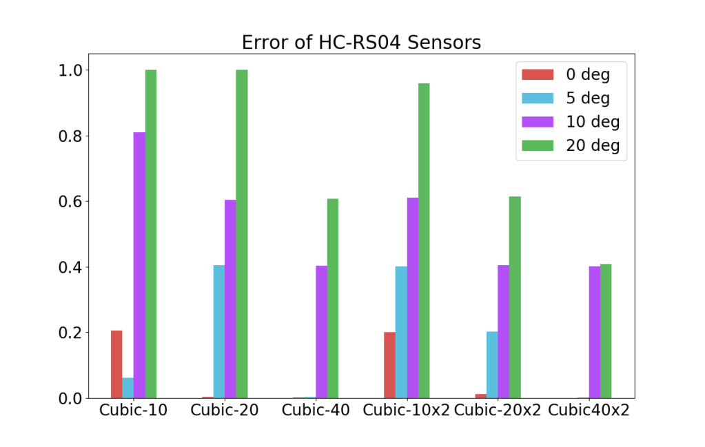
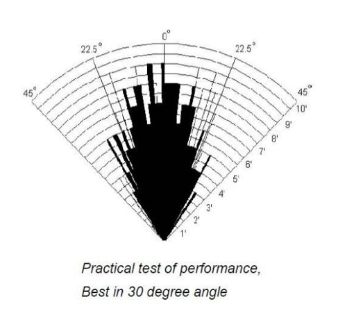
Furthermore, we manually tested the accuracy of the distance readings and found previous studies to verify our findings. As discovered in both our experiments and research, the distance sensor is most accurate within a 20 degree angle and within approximately 6’. Considering the situation of a car pulling into a garage, this is well within our range, however, for liability purposes, the instructions for Prevent-A-Dent will state to allow for an error of +/- 1” for any given reading.
Conclusion and Future Improvements
In the future, there are a number of improvements we would make to the Prevent-A-Dent system in order to improve accuracy and ease of use. First, we would aim to further miniaturize the sensor component with an Arduino Nano, allowing it to fit in more locations around a garage. Additionally, integrating more than one sensor into the code to allow for even greater protection as well as having two sensors per module to create a greater angle of view for drivers would be ideal. Furthermore, as mentioned previously, having both modules automatically shut off when not in use would allow for significantly increased efficiency in regards to power. Finally, we also hope to add a sound component that provides an alert when the driver has nearly reached the sensor for those who have issues with vision.
Overall, the creation of Prevent-A-Dent yielded a number of lessons in addition to a well-functioning project. This being my first time experiencing the full engineering design process, I learned the importance of rapid prototyping and adaptability in responding to the variety of challenges that we faced. Also, though against my nature, I began to understand the value in simplicity and setting small goals rather than reaching immediately for more complicated and challenging objectives.
I would like to thank my group members, Professor Soltys, our TAs, and the ITL staff for always being available to provide assistance, offer new ideas, and making this project a fun and enjoyable experience from start to finish. Designing Prevent-A-Dent further emphasized the importance of teamwork and seeking help from those around us as key aspects to successful engineering.
